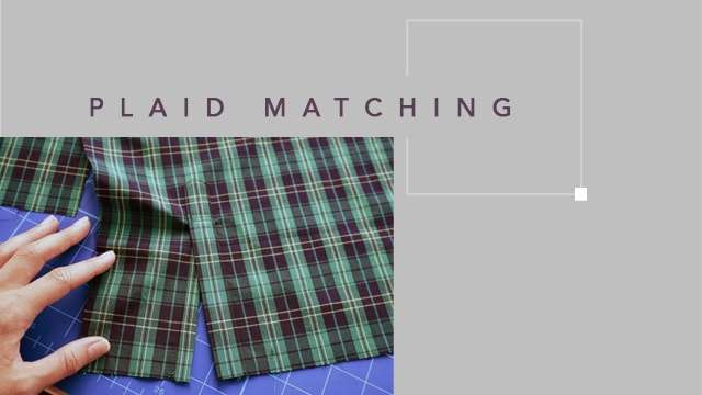
Plaid matching in adjoining components in any garment is an important requirement while using yarn dyed fabrics. Such matching requirements are achieved in cut components during spreading and cutting of the fabric. The common problem with checks is that the repeat size is not constant but variable. This is the experience/impression manufacturers have. If the repeat is not constant, we cannot plan a marker exactly on a repeat. But this is only really true for fabric coming from handlooms or old power looms and fabric finished using archaic methods. Fabric produced on industrial looms and finished using the correct method is normally of such good quality that we are able to plan markers exactly on the repeat, spread the fabric according to the repeat and cut the lay package later, obviating block cutting and relaying the pieces later for single piece matching.
There are various levels of technology available for various needs and for various scales of operation.
Basic Level of Technology
The basic level of technology is creating markers on a computerised marker generation system with matching points for plaid/checks and a provision for block cutting. The real size marker layout will be taken out from the plotter. During spreading of fabrics using a spreader or manually, the fabric is laid with one side of the selvedge aligned. This way, the best possible lengthwise stripe match is realised. The paper marker is kept on the lay and a straight knife used. During cutting, single or dual pattern blocks are cut using a straight knife. Then the stack component is relaid on a pintable, manually matching stripes, either length or widthwise, layer by layer. If a pintable is not used, then during re-laying, pins are often used from the top of the stack to avoid interplay slippage in the stack. Then precision cutting is done using a band knife.
|
Technology required for basic level: |
|
Makes and Models |
Features and Specification of Machinery and Equipment |
|
Apparel CAD |
Pattern design system (PDS), grading and marker making module. Interactive nesting on plain fabrics - Interactive or automatic nesting on matched fabrics.Windows® 2000 Server ,SQL server ; 2000 DatabasePentium IV 2 GHz, 2 GB extensible to 4 GB RAM; Disc size: 10 GB for installation, 10 GB per 1,000 files; High Speed 100 Mbps network recommended; Client workstation requirements: Windows XP Professional, 100 BaseT Ethernet Adapter with TCP/IP (10 MB possible, but with lower performance), 4 button mouse, standard keyboard, CD ROM drive (optional for installation) |
|
Plotter |
Printing width 72” (1.83m) to 90” (2.28m), Piezo-electric printing heads, Automatic cleaning of heads, Ink cartridge changeover during printing, Compliance CE, UL & CSA CE, UL & CSA; Connection modes: RS 232 or USB; Windows 2000 or XP, Productivity requirement: 30-100 m/hour for a 1.60 m width for normal quality and 17-60 m/hour for high quality; Max paper roll weight 40 kg; Max paper roll diameter 20 cm; Paper type: Standard paper (40g/m²), recycled paper or fuse paper, Plot resolution: 90 dpi normal quality, 180 dpi high quality, Compatibility: ASTM standard HPGL; Cutfile plots: RS274D, ISO 6983; Plot management: locally, on a server, via Internet |
|
Spreader |
Mechanised or semi-automatic spreader, Electronic positive fabric feeding, Pre-feed: not available; Max spreading speed: 100m/min.; Max spreading high cut: 20cm; Spread- high folded spread system: 16cm; Universal cut: 16cm; Max roll diameter: 60cm; Max roll weight: 150 kg |
|
Straight Knife |
Knife sizes: 5”, 6”, 7”, 8”, Rated voltage: 110, 220, 380V; Rated frequency: 50/60Hz; Power: 550/750W; Cutting height: 110/235mm; RPM: 2,800 / 3,300 min; Horsepower: 0.65hp, Single phase; 0.93hp, Three phase. |
|
Block Pin Table |
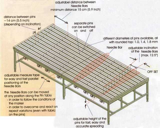
These are tables of size 1.8 m x 1.2 m to 1.8 m x 3.6 m or can be fabricated as required. Tabletops are two - layered. The top layer is fixed with the table stand and has pinholes in both horizontal and vertical grids. The bottom layer has pins mounted on similar horizontal and vertical grid points. The bottom layer of tabletop can be raised or lowered while the pins potrude through the pinholes. Here also, pins can be dismantled if not required at certain grid points. There are colour grid lines ruled into 5 cm squares on the table top with an option to use Laser light guides, which makes pattern matching between two needles easy. The height of the needle can be adjusted to a maximum of 100 mm by an operating handle. Needles are specially coated to avoid damaging fabric. |
|
Band Knife |
Variable speed control of the blade to facilitate cutting of diverse fabrics. The blowing facility from the table top makes the airspace under the fabric, facilitating its manoeuvring. Band knife should be equipped with a special detector (responsible for the work of band knife blade) and a special protecting blade system (protects band knife blade from escape from the course) in case of breakage. Stainless steel protective gloves of the right size should be worn by the user.Variable Speed Control Main Motor: 380V – 750W – 1440 RPM; Blower Motor: 210V – 380W – 2880 RPM; Knife Size: 0.45 x 10 x 3500 mm;Table Size: 1200 x 1600 mm; Height: 720 – 850 mm; adjustable gap between the blade and carrier arm 700 mm; Cutting capacity maximum 180 mm; Dimension of the band knife blade 3500 x 10 x 0.45 mm |
Technology required for basic level:Apparel CAD, plotter, spreader, straight knife, Block pin table and band knife
Intermediate Level of Technology
The intermediate level of technology is creating markers on a computerised marker generation system with matching points for plaid/checks. A full size marker plot is taken on a paper and the fabric is manually spread (no spreader is used) using continuous pin tables for perfect alignment of the plaids during spreading. First the nedle bars are adjusted according to the marker. The first lay is under lay-paper, then the fabric is pinned from centre to selvedge, layer by layer. The lay is cut using a straight & band knife combination. The pintable preparation part of the process is supported by software, first by PinIT software from Veith Systems, then by one of the known CAD-systems, then again by PinIT. The actual spreading and matching of the fabric on the VEITH Pin Table is a manual process. The lay packages can be cut manually by the straight and band knife combination. Small components are block cut using the straight knife, then the stack is transferred to the band knife. To avoid interplay slippage, Veith pinblocks are used. Finally, small components are cut using the band knife.
|
Technology required for intermediate level: |
|
Makes and Models |
Features and Specification of Machinery and Equipment |
|
Apparel CAD |
Automatic Marker Generation System for all types of fabrics (especially checked) which automatically calculates the exact position of the pattern components on the fabric. The pattern-making and marker making software should be fully integrated. For example, any modification to a piece in PDS is immediately reflected in Marker Making System. Fully automatic nesting based on latest technologies, respecting fabric and garment constraints |
|
Plotter |
Same as above |
|
Continuous pintable |
Standard modular table size 170cm x 404 cm; Extra widths 184, 198, 212, 226 and 240 cm available. Length is adjustable with 2m modules. Needle diameter is colour coded (1.0, 1.4, 1.8 mm). Height of needle up to 10cm. Extra fine needle with 0.6mm available. Rollstand or Turn-Table with extra device for underlay paper and polyethylene film. Air-flotation (2) for easy transport of heavy lays; Additional needle-bars one-side parallel adjustment of needle-bar belt-drive for automated transport |
|
Straight Knife |
Same as above |
|
Band Knife |
Same as above |
Technology required for intermediate level:Apparel CAD, Plotter, continuous pintable, straight knife and band knife
Highest level of technology
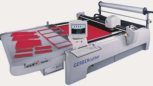
The highest level of technology is by creating markers on a computerised marker generation system with matching points for plaid/checks and spreading the fabric using a continuous pintable to prepare lay packages similar to theintermediate level. Here the lay will be cut using CNC-Cutter (CAM) which is equipped with a camera system in order to do the final adjustment (2-3 mm) in the position of the patterns related to the lay package. This step needs the operator and can be understood to be semi-automatic. The digital camera and associated light box analyse the exact position of motifs on the cutting surface. The on-cutter scanner detects the fabric’s actual motif, analyses distortion, modifies markers and geometry of pieces in real time based on the fabric’s physical characteristics and automatically launches the calculation and cutting process. This eliminates need for material to be ‘block’ cut and the result is absolutely astonishing regarding accuracy. It reduces labour and material costs because there is no need for skilled operators to manually match fabrics.

It may be noted that different levels of technology do not result in different levels of quality; rather it is time and manpower that is saved while using the higher levels of technology. In case of striped knitwear, however, a continuous pintable is preferred over a block pin table as the stripes in circular knit fabric are always at an angle and only a continous pintable offers angular alignment of pins.

|
Technology required for higest level: |
|
Makes and Models |
Features and Specification of Machinery and Equipment |
|
Apparel CAD |
Same as above |
|
Continuous pin table |
Same as above |
|
CNC Cutter |
Fabric lay thickness (compressed) 2.5 cm 1.0 in; cutting speed (maximum) 46 m/min 1800 in/min; cut width 1.7 m 67 in and cut length 1.7m 67 in. Average throughput (depending on application) 10.2 m/min 400 in/min; Head acceleration (maximum) 3.7 m/s2 3/8 g;Table weight: 2,554 kg 5,618 lbs;Table heights - available 75-90 cm in 5 cm increments ± 30-36 in 2 increments; Average Consumption 10 KW for 3-phase system; Compressed Air 11.3 litres/min @ 6.8 bar 4 SCFM @ 100 PSI; Temperature (maximum) 43ºC 110ºF; Humidity (maximum) 95% (non-condensing); Vacuum System 760 m (2,500 ft) above sea level; Noise 75 dBA |
|
On-Cutter Scanner |
On-cutter scanner system for stripes, checks, prints and plaids carries out matching and cutting operations simultaneously, increasing accuracy and throughput in your cutting room.This optional, on-cutter system works with a CNC cutter to improve the finished quality of plaid- and stripe-matched products by compensating for fabric irregularities and delivering thread-to-thread accuracy of cut parts. |
|
Completely automates the matching process thereby eliminating errors that can occur when using manual or semi-automated matching processes. |
|
Simplifies and enhances matching and cutting with an intelligent vision system. |
|
Zooms in on critical areas for added precision with advanced camera and optics system. |
|
Achieves precise matching even through plastic overlay with state-of-the-art lighting system and imaging techniques. Increases accuracy with PicturePerfect technology that corrects for distortions in the fabric spread, so the processed image appears as it will on the finished part. |
|
Maintains complete control of matching. |
|
Makes corrections for irregularities in the fabrics repeat pattern. |
|
Establishes piece-to-piece matching relationships based on a pattern pieces relationship to the fabric or to other pattern pieces |
Technology required for higest level:Apparel CAD, Spreader, continuous pintable, CNC cutter with On-cutter scanner
Value for Money
The higher the technology level, the better the benefit in terms of productivity realised. The Return on Investment for different equipment differs, based on scale of operation and types of merchandise produced, etc. Here I will give examples of two generic pieces of equipment.
Example ROI for Automatic Spreader
1) Fabric Saving
We can save fabric on the spreading machine by making longer layers; e.g., if we have to make 3 m long marker with 200 plies, 2 cm end loss on each side is 800 cm in total. Using an automatic spreader, we can make longer layer (depending on the fabric), say 12 m and reduce the plies by 150. Now the end losses will be 50×4 = 200cm, thus saving 600cm fabric or 1.0% of fabric. Assuming that splicing also generates around 0.75% of savings, total savings by using the spreader is 1.75%.
Suppose average fabric price is Rs 50 per metre and spreading 5,000 m per day, it will give a saving of (1.75% x 50 x5000) = Rs 4,375 per day = Rs 13,12,500 per year (300 working days per year).
2) Manpower Saving
With the automatic spreader we can manage with one operator and one helper. This means a saving of salaries of at least 10 operators /helpers. If they get an average of Rs 3,000 per month, it means a saving of Rs 30,000 per month or, Rs 3,60,000 per year.
Average saving per year = Fabric saving + Salary Saving = Rs 13,12,500 + Rs 3,60,000 = Rs 16,72,500
Cost of automatic spreader = Rs 20,00,000 Return on Investment = 20,00,000 / 16,72,500 = 1.195 years
Apart from the above, precious time is also saved and intangible benefits like quality improvement accrue.
Example ROI for Continuous Pin Table
As we can avoid most blocking tolerances, we work with smaller patterns, i.e., fabric consumption is reduced. This depends on the size of the repeat – according to our experience, 3% saving is an average figure. But we argue normally with just 2% when talking to customers in order to be on the conservative side and still get a good ROI.
2% (saving) x 1.8 m (consumption) x 550 (shirts/day/ 8h-shift) x US$3.5 (price of fabric / m) = US$6,930 saving per day; with an investment of US$20,000 , we get a ROI of 288 days, which is less than 9 months, even though we did not include the better quality and the higher productivity in our calculation.

Leave a Reply